In our latest vlog, Camille sits down with John Watton to discuss our new Rapid Forge DesignTM software, as well as give a demonstration of its powerful capabilities. Watch the vlog above and be sure to take a look at the case study for more information.
Continue reading Rapid Forge Design vlog demonstrationCategory: Our Work
Search results for Hill Engineering blog posts under the subject category our work
Mechanical stress relief of aluminum alloys
As we discuss in a related case study, aluminum alloy heat treatment is a three-step process designed to achieve the desired properties. The process involves: 1) solution heat treatment (SHT) at an elevated temperature below the melting point, 2) quenching in a tank of fluid (e.g., 140-180°F water), and 3) age hardening. While providing good properties, the heat treatment has the negative side effect of creating bulk residual stress and distortion. These side-effects are a direct result of non-uniform cooling during the rapid quench. One approach to mitigate this problem is the application of a post-heat treatment mechanical stress relief process. In addition to modeling the heat treatment process, our analysis tools can support evaluation and optimization of mechanical stress relief processes.
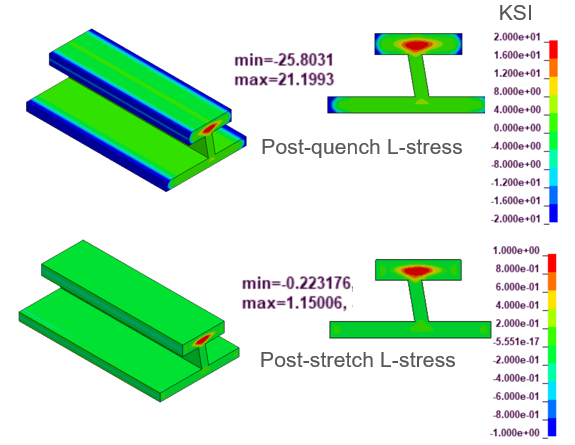
Mechanical stress relief is practical for many aluminum alloy products as a means of reducing bulk residual stress. For products with a uniform cross section, such as most extrusions, plate, and bar stock, the material can be stretched on the order of 1% to 5% using special equipment. The figure below shows an example extrusion section with bulk residual stress (top) along with the remaining residual stress after mechanical stress relief (bottom). Note, the use of different color scales because the residual stress magnitude changes so significantly. This figure illustrates our capability to model post-quench and post-stretch residual stress.
For other products such as forgings, an alternative stress-relief process using a compressive cold work stress relief can be employed. For a hand forging this is usually achieved using open-dies comprised of mostly flat surfaces. Post-quench, the hand forging is subjected to 1% to 5% compression often in an overlapping fashion.
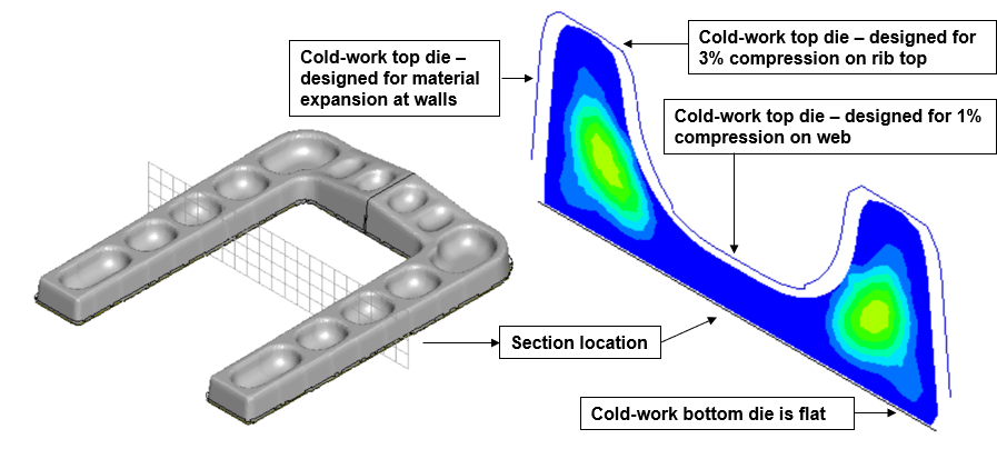
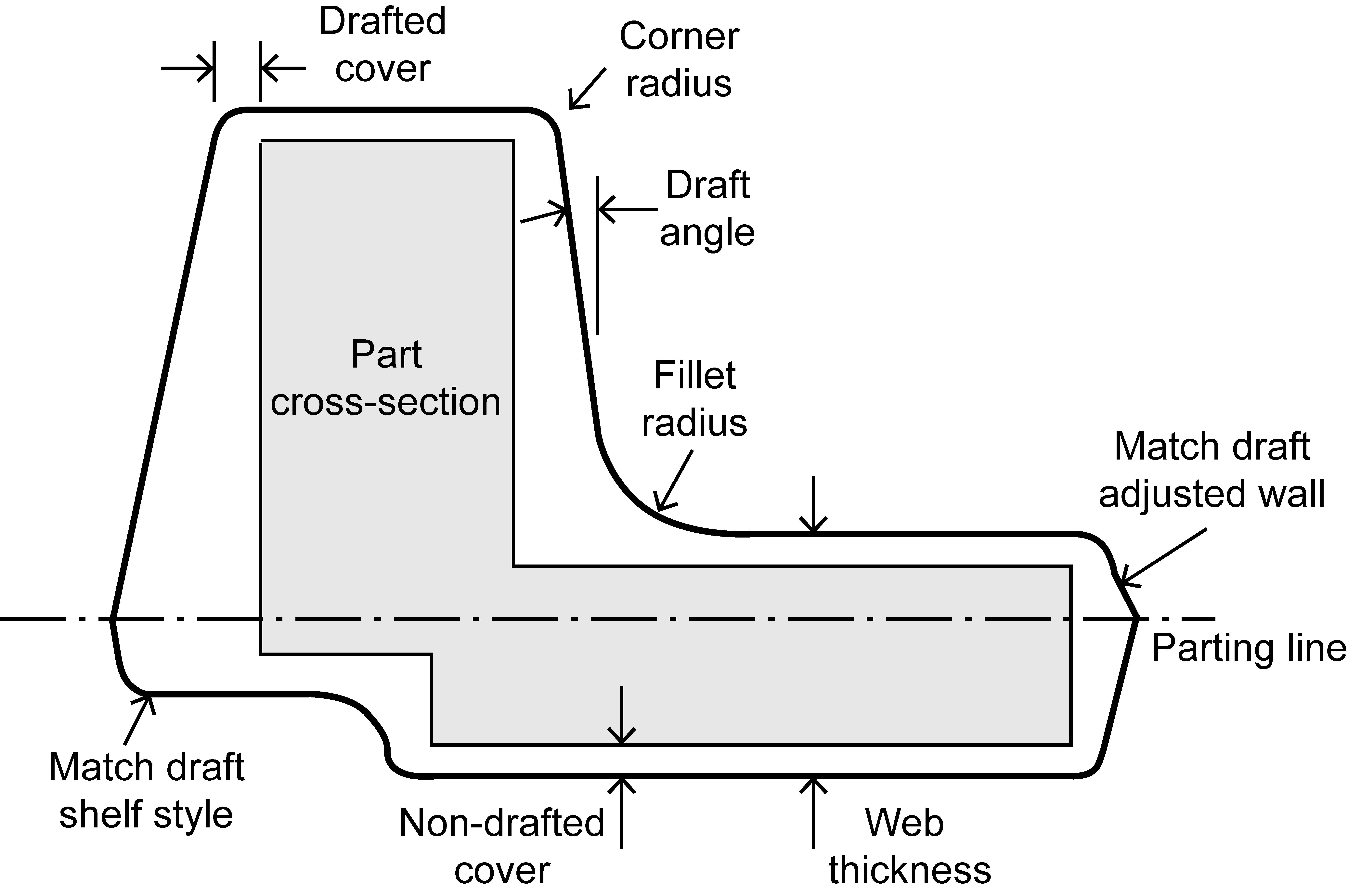
On the other hand, an impression-die forging usually requires a more complex process that involves a cold-work die set. Such die sets are designed to impress 1% to 5% cold-work. Typically, the compression is on the order of 1% in thinner web sections and 3% in thicker rib sections. Since the forging will be at room temperature for the compression (therefore the term – cold-work) it does require higher press loads than one sees in the hot forging operation. The following figure illustrates the elements of a cold-work die set.
In a previous case study, we demonstrated our capability to predict post-quench residual stress and distortion for an example forging. The effect of mechanical stress relief using compression dies on that same example forging is shown below. The post-quench residual stress (left) reaches as high as 20.0 ksi in this aluminum 7075 simulation. The post-cold-work residual stress (right) is significantly reduced. The reduced residual stress level in the stress-relieved state has significant advantages in terms of ease of machining (reduced distortion) and improved part performance.
If this example relates to your production challenges, or if you have any questions about how these results might affect your projects, please do not hesitate to contact us. We would also be happy to answer any questions that you may have.
Case Study: Aluminum forging cold-work stress relief
As we discuss in a related case study, aluminum alloy heat treatment is a three-step process designed to achieve the desired properties. The process involves: 1) solution heat treatment (SHT) at an elevated temperature below the melting point, 2) quenching in a tank of fluid (e.g., 140-180°F water), and 3) age hardening. While providing good properties, the heat treatment has the negative side effect of creating bulk residual stress and distortion. One approach to mitigate this problem is the application of a post-heat treatment mechanical stress relief process.
Continue reading Case Study: Aluminum forging cold-work stress reliefBAMpF Rebranding
Hill Engineering completed a rebranding process for our industry leading fatigue analysis software. The process produced a new name, BAMpFTM (Broad Application for Multi-point Fatigue), and a new logo.
Continue reading BAMpF RebrandingRapid Forge Design
Hill Engineering’s Rapid Forge Design™ software is an automated tool for fast and reliable design of 2-piece, closed-die impression forgings. Rapid Forge Design™ reads the final part geometry and automatically designs a forging according to accepted industry guidelines and user inputs. Rapid Forge Design™ is intended for use by forging suppliers and forging consumers/OEMs.
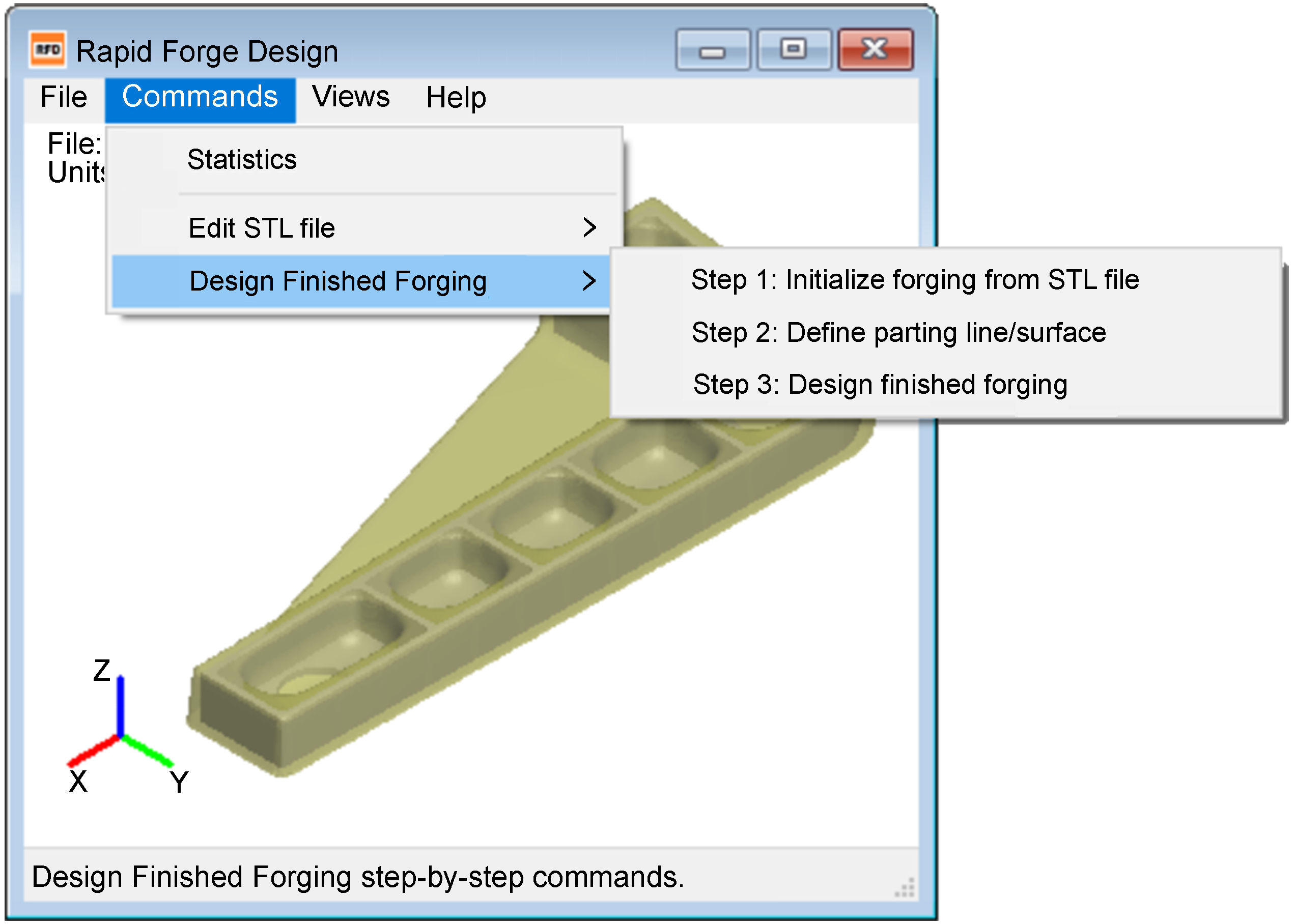
The Rapid Forge Design™ software comes with a user-friendly, graphical interface that allows for forging designs using a simple, 3-step, menu guided approach.
The inputs to Rapid Forge Design™ are the 3D geometry of the machined part (to be manufactured from the forging) and critical, user-defined parameters that allow for customization of the resulting forging design (e.g., minimum thickness and minimum radius values).
The forging design is generated by Rapid Forge Design™ according to a set of prescribed, industry-accepted design rules. After the user inputs are provided, the automated forging design process is completed by Rapid Forge Design™ in minutes without any further user intervention. With this approach, Rapid Forge Design™ enables the design of forgings with significantly less effort than existing manual processes.
Rapid Forge Design™ outputs the 3D geometry of the forging and a host of useful forging statistics and properties including volume, plan view area, periphery length, heat treatment section thickness, and other dimensional information. These metrics are essential to support the quoting process (material producers) and planning and costing activities (OEMs).
The preliminary forging designs produced by Rapid Forge Design™ can be used as the starting point for the finished forging’s more detailed design and tooling CAD files.
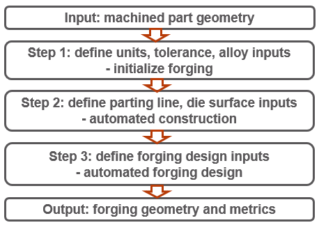
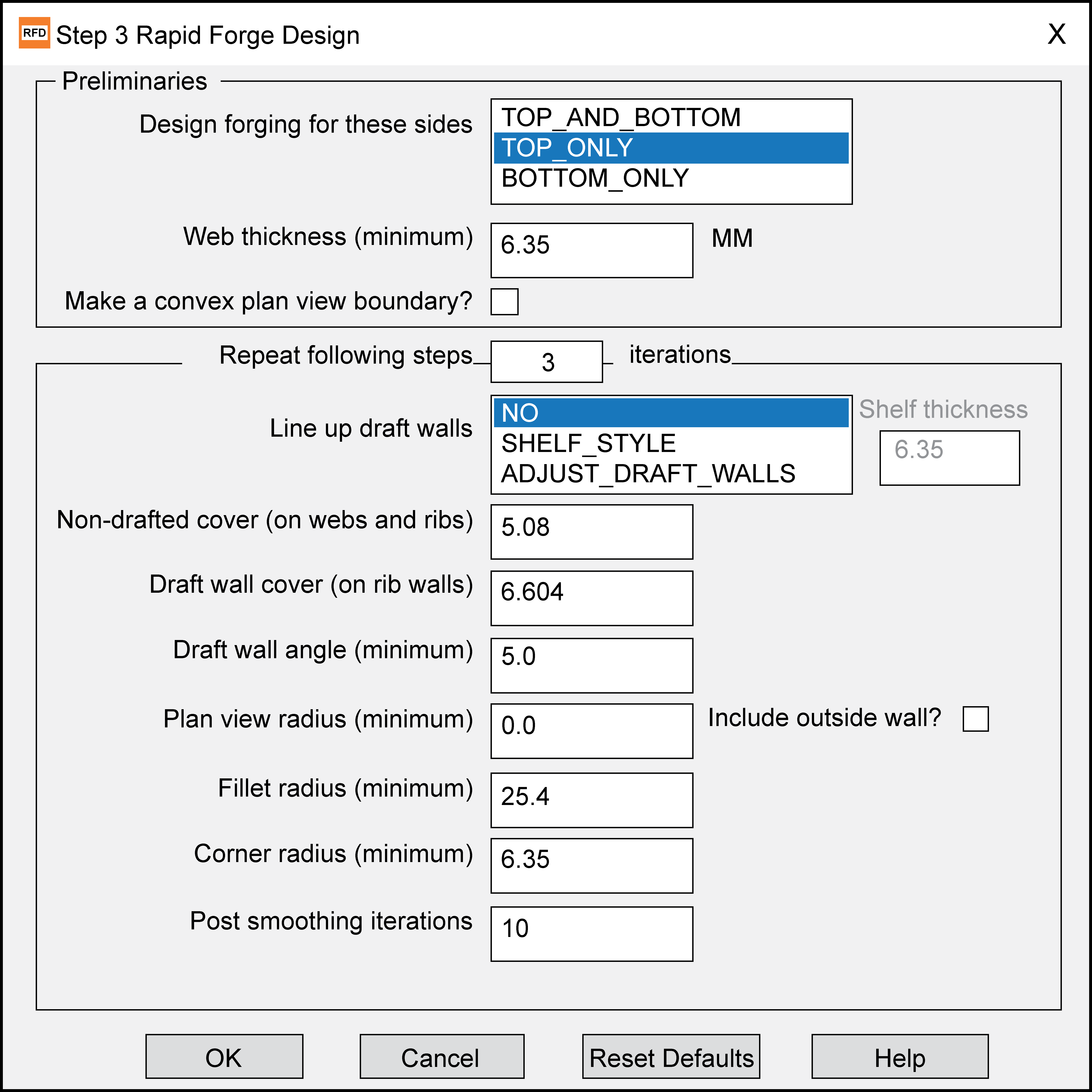
The Rapid Forge Design™ process is outlined in the flowchart below. The operator can input and customize important design parameters including: web thickness, draft wall cover, draft wall angle, plan view radius, fillet radius, and corner radius. Default values are provided based on alloy dependent industry standards. Help menus provide additional support and guidance, where necessary.
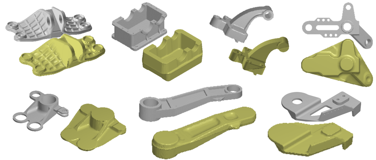
Numerous examples taken from publicly available CAD files come with the software. The following are a few illustrations showing the ability of Rapid Forge Design™ to effectively produce forging designs for a wide variety of supplied final part geometry.
https://www.youtube.com/watch?v=wV3Vb4-DUV4
To place an order for Rapid Forge Design™ related goods and services, please contact us.
Case Study: Rapid Forge Design
Hill Engineering’s Rapid Forge DesignTM software is an automated tool for fast and reliable design of 2-piece, closed-die impression forgings. Rapid Forge DesignTM reads the final part geometry and automatically designs a forging according to accepted industry guidelines and user inputs. Rapid Forge DesignTM is intended for use by forging suppliers and forging consumers/OEMs.
Continue reading Case Study: Rapid Forge DesignCase Study: Aluminum forging quench modeling
Aluminum alloy heat treatment is a three-step process designed to achieve the desired properties. The process involves: 1) solution heat treatment (SHT) at an elevated temperature below the melting point, 2) quenching in a tank of fluid (e.g., 140-180°F water), and 3) age hardening. While providing good properties, the heat treatment has the negative side effect of creating bulk residual stress and distortion.
Continue reading Case Study: Aluminum forging quench modelingAluminum forging quench modeling
Aluminum alloy heat treatment is a three-step process designed to achieve desired properties. The process involves: 1) solution heat treatment (SHT) at an elevated temperature below the melting point, 2) quenching in a tank of fluid (e.g., 140-180°F water), and 3) age hardening. While providing good properties, the heat treatment has the negative side effect of creating bulk residual stress and distortion. These side-effects are a direct result of non-uniform cooling during the rapid, time-dependent quench. Since there is an unavoidable difference in cooling rates between near-surface and internal areas, thinner versus thicker sections, locations first submerged versus those submerged last, and vertical versus horizontal surfaces, the generation of bulk residual stress and distortion is unavoidable. Oftentimes there are so many variables in play it can appear as though there is a high degree of randomness in the process if things are not carefully controlled. Our analysis tools can help.
The focus of this case study is the quench distortion of an aluminum aerospace forging. Using our modeling tools, we were able to capture the significant post-quench distortion in the forging, which is shown in the figure below. A rapid immersion quench, evenly applied, results in a very distorted and bowed output.
Clearly, alternatives needed to be explored to mitigate the large amount of distortion. We considered several possibilities: slowing the cooling on one side (with a coating), removing the webbing before the quench (with machining), increasing the thickness of the webbing, or redesigning the forging with back-to-back symmetry by putting two parts into one forging. However, real-time physical experimentation of multiple options would be expensive and time consuming.
With modeling tools, we were able to quickly and effectively identify the most promising alternatives for improvement.
In this case, the biggest improvement came from removal of the webbing. The webbing is necessary for some of the initial forging operations, but does not need to be retained. It does not provide any coverage of the customer’s final post-machined part, and it is not necessary for heat treatment. Removing the webbing (i.e. cutting it off) prior to heat treatment requires an extra machining operation, but that is relatively inexpensive. As seen in the next figure, removing the webbing before quench resulted in a post-quench distortion that is remarkably reduced.
The advantage of pre-production simulation is that problems can be found and solved beforehand, and the robustness of the proposed solutions can be tested and quantified.
Post-quench distortion is driven by bulk residual stress. That stress is created during the quench due to uneven cooling. Near surface cooling is much faster than the internal cooling of the part. This is unavoidable. However, using our modeling tools, the quench-induced residual stress can be predicted.
This predicted bulk residual stress is useful in follow-up simulations of post-machining distortion and part performance. The next figure shows the principal bulk residual stress as seen in section planes throughout the forging. Note that the residual stress reaches as high as 20.0 ksi in this aluminum 7075 simulation. This residual stress is post-quench and absent of any mechanical stress relief operations that are typically performed in subsequent steps.
If this example relates to your production challenges, or if you have any questions about how these results might affect your projects, please do not hesitate to contact us. We would also be happy to answer any questions that you may have.
Analysis of distorted aerospace part
We recently uploaded a new case study on the topic of part distortion caused by residual stress during machining. We wanted to dive a little deeper into the topic with an analysis of a distorted aerospace part. Here is what we found. Continue reading Analysis of distorted aerospace part
Case Study: Multi-step machining distortion modeling
Distortion of parts during the machining process is a significant problem faced by many machining vendors. This phenomenon typically results from the release and redistribution of residual stress in the material once the part is unclamped from the machine table. When not accounted for, machining distortion can lead to out-of-tolerance parts that either require reworking, or have to be scrapped. Continue reading Case Study: Multi-step machining distortion modeling