Near-surface residual stress data is critical when assessing material performance, optimizing design, validating models, evaluating field failures, and executing quality assurance programs. Hill Engineering’s DART™ is an industry-leading tool for efficient, precise, and reliable near-surface residual stress measurements. The DART™ overcomes limitations of existing residual stress measurement equipment and includes everything required to perform state-of-the-art measurements in accordance with industry specifications.
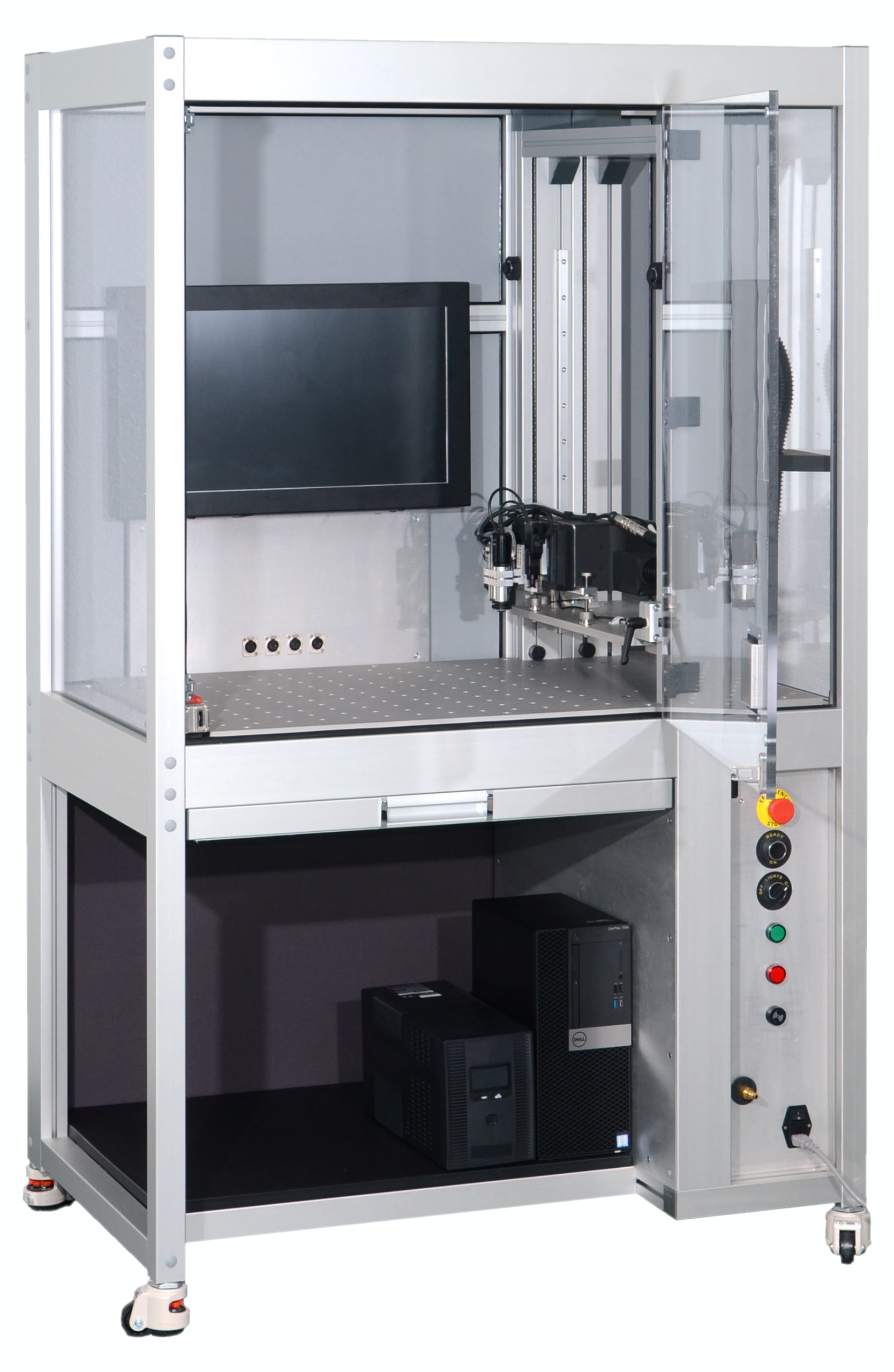
Hill Engineering’s DART™
A single DART™ can perform near-surface residual stress measurements using multiple techniques including hole drilling
and TRUEslot® methods. This flexibility is helpful when requirements change or new applications arise. The DART™ executes hole-drilling residual stress profile measurements in accordance with ASTM E837, providing a depth profile of the three in-plane residual stress components in a single measurement. TRUEslot® is a novel technique, like hole-drilling, but simpler and more precise. TRUEslot® provides a depth profile of one stress component per measurement.
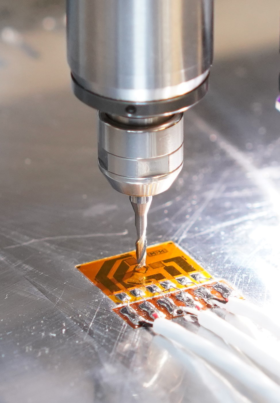
Hole drilling measurement example
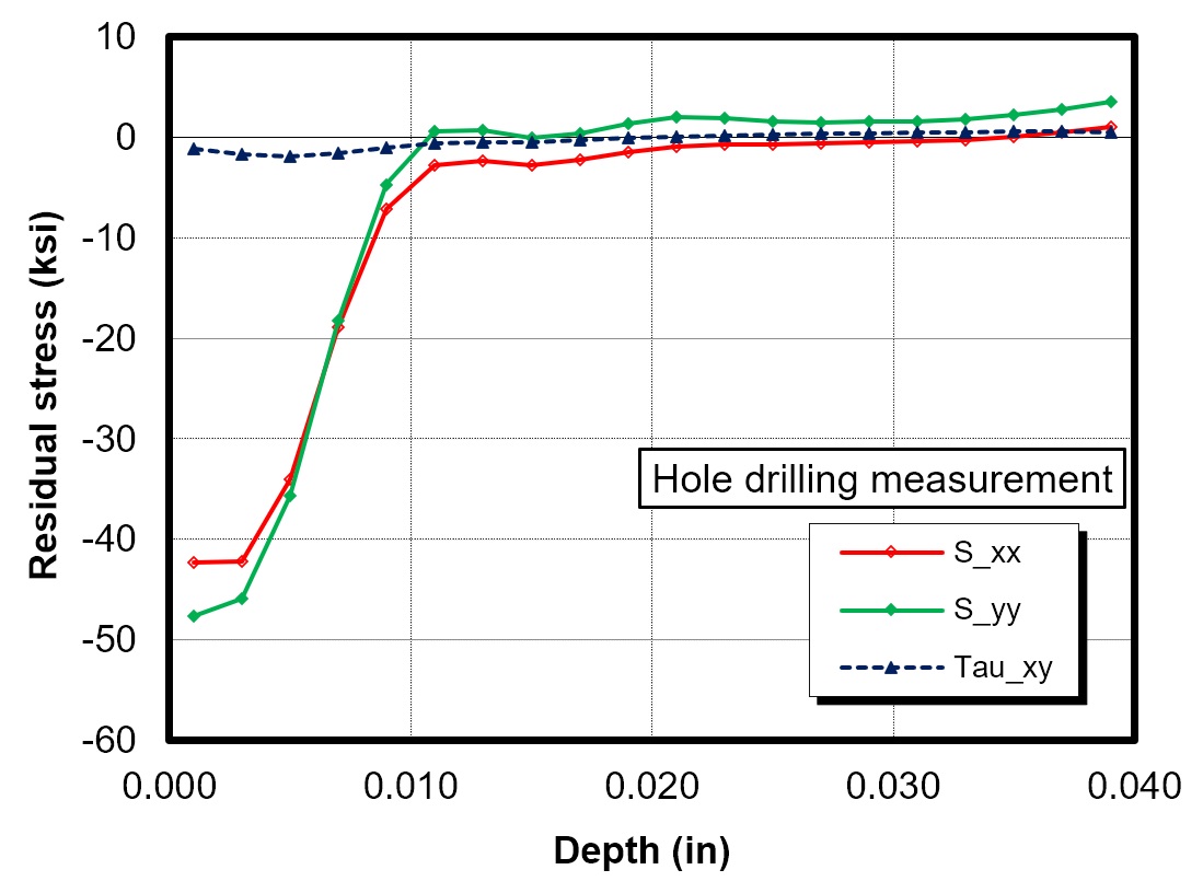
Hole drilling results example
Intuitive
Residual stress measurements with the DART™ are easy to complete. A user interface guides you through set-up, then takes over for automated measurement execution and residual stress calculation.
Efficient
With measurements completing in less than 60 minutes, the DART™ excels in the production quality management environment. Automated data capture, processing, and archiving provide you with residual stress results instantly.
Reliable
Featuring advanced cutting strategies and real-time quality checks, the DART™ gives you confidence in your residual stress data.
Features
• Hole drilling residual stress measurements according to ASTM E837
• TRUEslot® residual stress measurements
• Positional accuracy: ± 0.001 in.
• Works on most materials including: aluminum, titanium, steel, stainless steel, and nickel alloys
• Custom fixtures can be integrated to meet the needs of individual applications
• NFPA 79 compliant
Software
Each DART™ includes a complete software package that enables efficient and repeatable residual stress measurements for high-volume or single-use applications. DART™ software is designed for ease-of-use, while maintaining flexibility to meet your measurement needs and providing controls to maximize reliability. An operator defines the measurement location, the type of measurement (TRUEslot® or hole-drilling), and inputs the key measurement details. Following set-up, the software automatically controls the incremental material removal process, acquires the experimental data, computes residual stress, and outputs a test report. The entire process is significantly more efficient than other available tools.
DART™ produces the highest-quality residual stress data available
Precise engineering and extensive use of automation within the DART™ provides a demonstrated 50%+ improvement in measurement repeatability relative to other hole drilling test equipment. Hole drilling and TRUEslot® measurements performed using a DART™ have been shown to be 60%+ more repeatable than X-ray diffraction measurements.
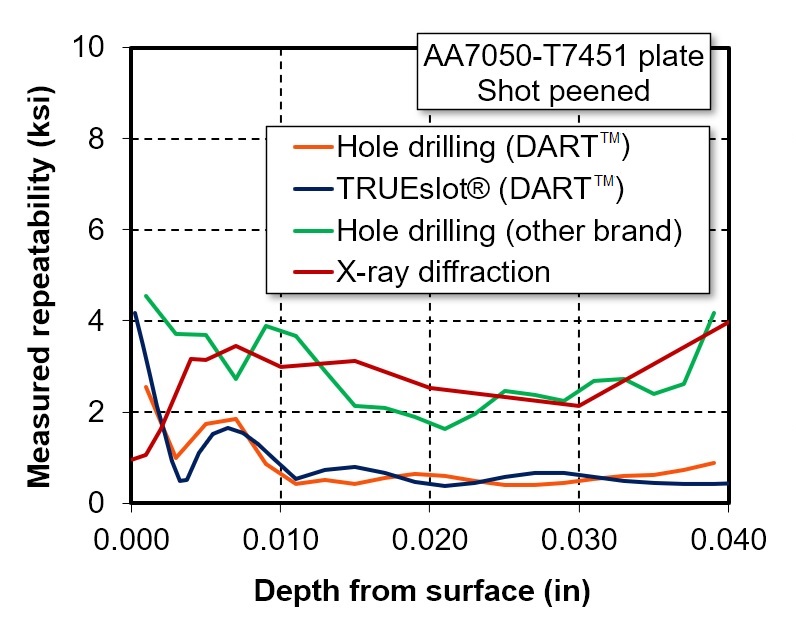
DART™ outperforms its competitors in RS measurement repeatability
The DART™ has proven to meet our high internal standards for data quality and is currently in use in multiple facilities throughout the world. It could be in your facility soon.
To place an order for DART™ related goods or services, please contact us.
Download a DART™ brochure here
The following are a list of patents pertaining to DART™ and TRUEslot®. Additional patents are pending for other international jurisdictions.
United States
- US10900768B2 – Systems and methods for analysis of material properties of components and structures using machining processes to enable stress relief in the material under test
Japan
- JP7258393B2 – Analysis that enables stress relaxation of the material under test
- JP2023025055A – Analysis that allows stress relaxation in material to be tested