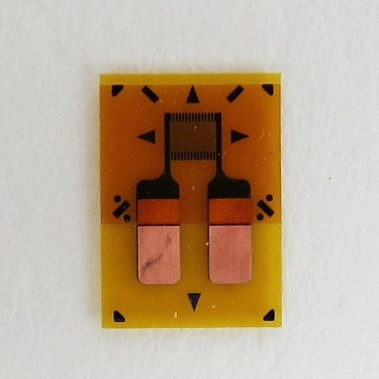
Strain gages are a key component of many of the residual stress measurements that we perform at Hill Engineering. These small but mighty sensors can also be used for other experiments, and this is something that we highlight in our recent case study.
As we’ve mentioned in a previous blog post, the most common type of strain gage contains a grid of conductive material, which when resting, exhibits a particular known resistance. With this knowledge, we can design a basic experiment to see how a strain gage works.
First, a gage is bonded to the surface of a specimen. Next, the specimen experiences some type of loading that causes it to deform. As the specimen deforms, the strain gage elongates or shrinks, which then changes the resistance in the grid. This change in resistance is realized through a strain reading and it is with this reading that we can infer different quantities, such as the amount of stress induced on the specimen.
For specimens like a beam that is being stretched and compressed, a strain gage can be used to infer the amount of elongation or compression it is experiencing. This capability makes strain gages perfect for measuring aircraft wing deflection and bridge cable creep, to name but a couple applications.
For the interested reader, we also highlight our video showing how we apply a strain gage to a simple measurement coupon.
