Cold hole expansion (CX or cold expansion for short) of fastener holes is a technique that has been widely used in the aircraft industry to improve the fatigue performance of structural components. The cold hole expansion process introduces compressive residual stress near the vicinity of the hole that slows crack growth and can significantly improve fatigue performance. The process induces plastic deformation near the hole from pulling an oversized mandrel through the hole. The elastic recovery of the surrounding material results in compressive residual stress near the hole bore surface that is balanced by tensile residual stress farther from the hole. The benefits of cold expansion on fatigue performance have been illustrated in several research studies. A correlation of fatigue crack growth at cold expanded holes is illustrated in [1].
This case study focuses on nonlinear process modeling of cold expansion using finite element analysis. An aluminum coupon with dimensions 50.8 x 50.8 x 6.35 mm (2.0 x 2.0 x 0.25 inch) and a hole in the center of diameter 12.12 mm (0.477 inch) is considered. The hole undergoes a 3.16% applied expansion during the cold hole expansion process, i.e., at maximum expansion, the hole radius is enlarged by 3.16%. Figure 1 shows the coupon geometry.
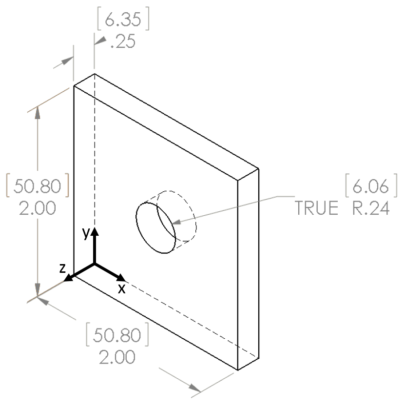
Coupon geometry used for cold hole expansion process modeling. Non-bracketed dimensions are in inches and bracketed dimensions are in mm.
The analysis considers the elastic-plastic behavior of the material, and uses a true stress-strain curve obtained from experimental tests using the specific material considered here. The material curve describes the material behavior under loading, and characterizes the hardening of the material as it is loaded past its initial yield strength.
Typically, fatigue cracks initiate at the edge of fastener holes. The hoop residual stress combines with applied loading to alter the crack driving force, and is important in a fatigue crack growth analysis considering cold expanded holes. The process model used here provides hoop residual stress as shown in Figure 2. A through-thickness map taken at the y = 25.4 mm (1.0 inch) plane is shown in Figure 2a, where high compressive residual stress is observed near the edges of the hole, while tensile residual stress arises farther from the hole edge to satisfy mechanical equilibrium. Figure 2b also shows the hoop residual stress, but at a xy midplane (z = 3.175 mm (0.125 inch)). The high compressive residual stress is localized near the hole edge, and is approximately axisymmetric. Taking a line plot of the hoop residual stress along a specified path provides more quantitative results, as illustrated in Figure 2c, where the path taken is at the y = 25.4 mm plane and at the mid-thickness of the plate (z = 3.175 mm (0.125 inch)). The curve in this plot is for the right side of the hole only (x > 30 mm).
The distribution shows peak compressive residual stress at the hole edge that decays and eventually becomes tensile. The peak compressive residual stress at the hole edge is -480 MPa (approximately -70 ksi). The size of the compressive residual stress zone, i.e., the distance at which the RS crosses 0 is about 4.4 mm (0.17 inch), which corresponds to about 0.7R (R = radius of the hole). Beyond the compressive residual stress zone, tensile residual stress develops with peak of about 115 MPa (approximately 17 ksi) at 7.2 mm (0.28 inch) away from the hole edge, which corresponds to 1.1R.
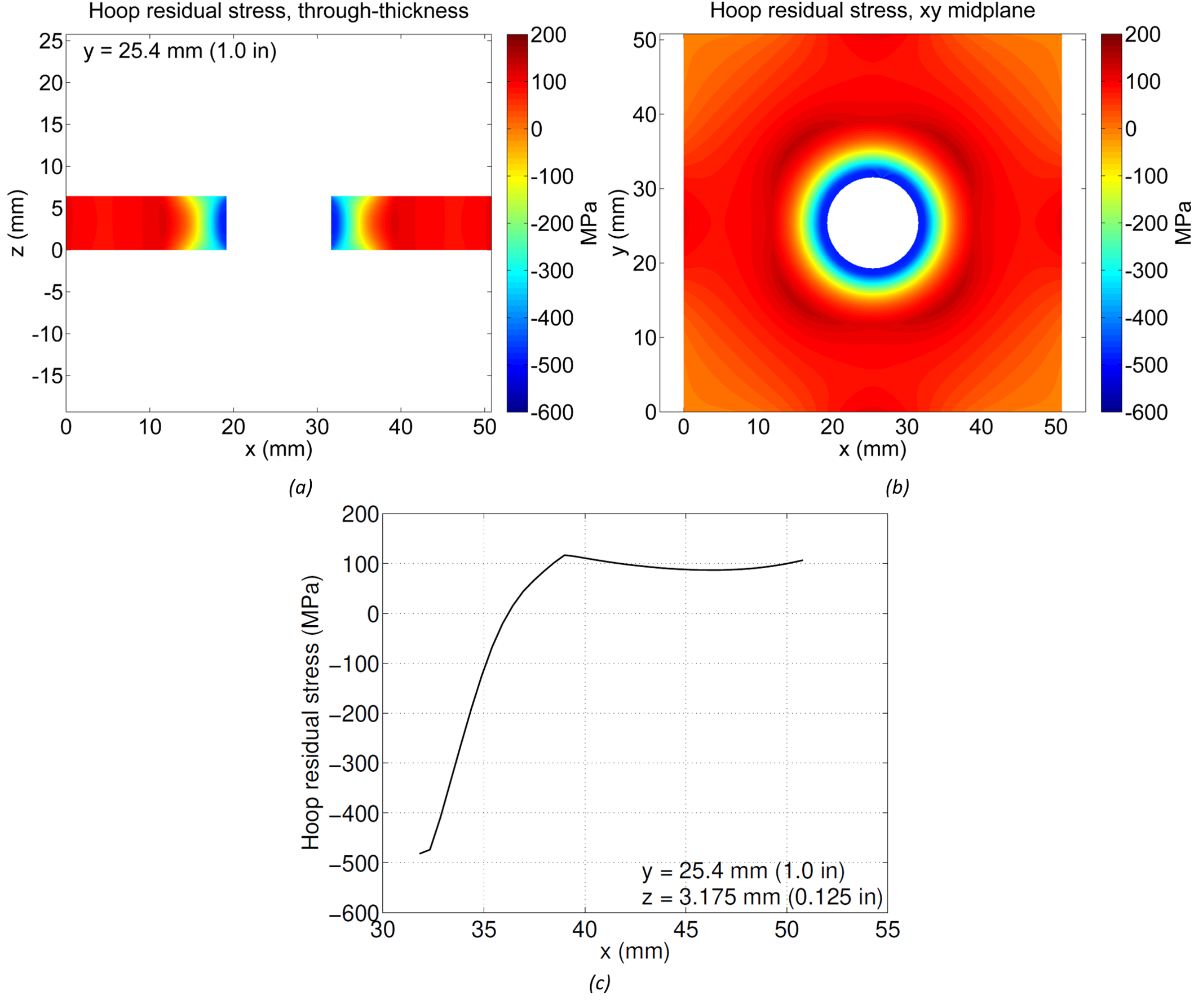
Hoop residual stress from process model with 3.16% applied expansion a) through thickness of coupon, b) on xy midplane at z = 3.175 mm (0.125 inch), c) line plot along x-direction at y = 25.4 mm, z = 3.175 mm
Having the process model established above, it is useful to evaluate the effect of the radial applied expansion level in the resulting hoop residual stress. Running the process model with a 4.16% applied expansion provides hoop residual stress as shown in Figure 3. Maps of the hoop residual stress are shown in Figure 3a and Figure 3b, and show slightly higher magnitudes of residual stress compared to the results in Figure 2a and Figure 2b. Figure 3c shows the line plot along the same path as for the previous model, and compares the results obtained with both levels of expansion. Overall, the higher level of expansion resulted in about 5% increase in peak compressive residual stress at the hole edge, and a 10% increase in the size of the compressive residual stress zone around the hole.

Hoop residual stress from process model with 4.16% applied expansion a) through thickness of coupon, b) on xy midplane at z = 3.175 mm (0.125 inch), c) line plot along x-direction at y = 25.4 mm, z = 3.175 mm
This case study focuses on process modeling using finite element analysis for prediction of residual stress from cold expansion of fastener holes. A process model is developed to simulate the expansion of the hole due to the mandrel pull-through operation, and the resulting hoop residual stress after elastic recovery of the material is presented. The model results show high compressive residual stress at the edge and vicinity of the hole, which decays with distance from the hole and eventually becomes tensile. Increasing the amount of applied expansion used in the model causes an increase in peak compressive residual stress at the hole edge, as well as an increase in size of the zone of compressive residual stress near the hole. Although only the hoop residual stress results are shown here, the process model provides full field solutions, and allows for evaluating residual stress from cold expansion through numerical simulation.
For more information about the study described above, our fatigue testing abilities, or any of our residual stress measurement techniques, please contact us.
[1] Stuart, D. H., Hill, M. R., and Newman Jr, J. C., 2011, “Correlation of one-dimensional fatigue crack growth at cold-expanded holes using linear fracture mechanics and superposition,” Eng. Fract. Mech., 78(7), pp. 1389–1406.